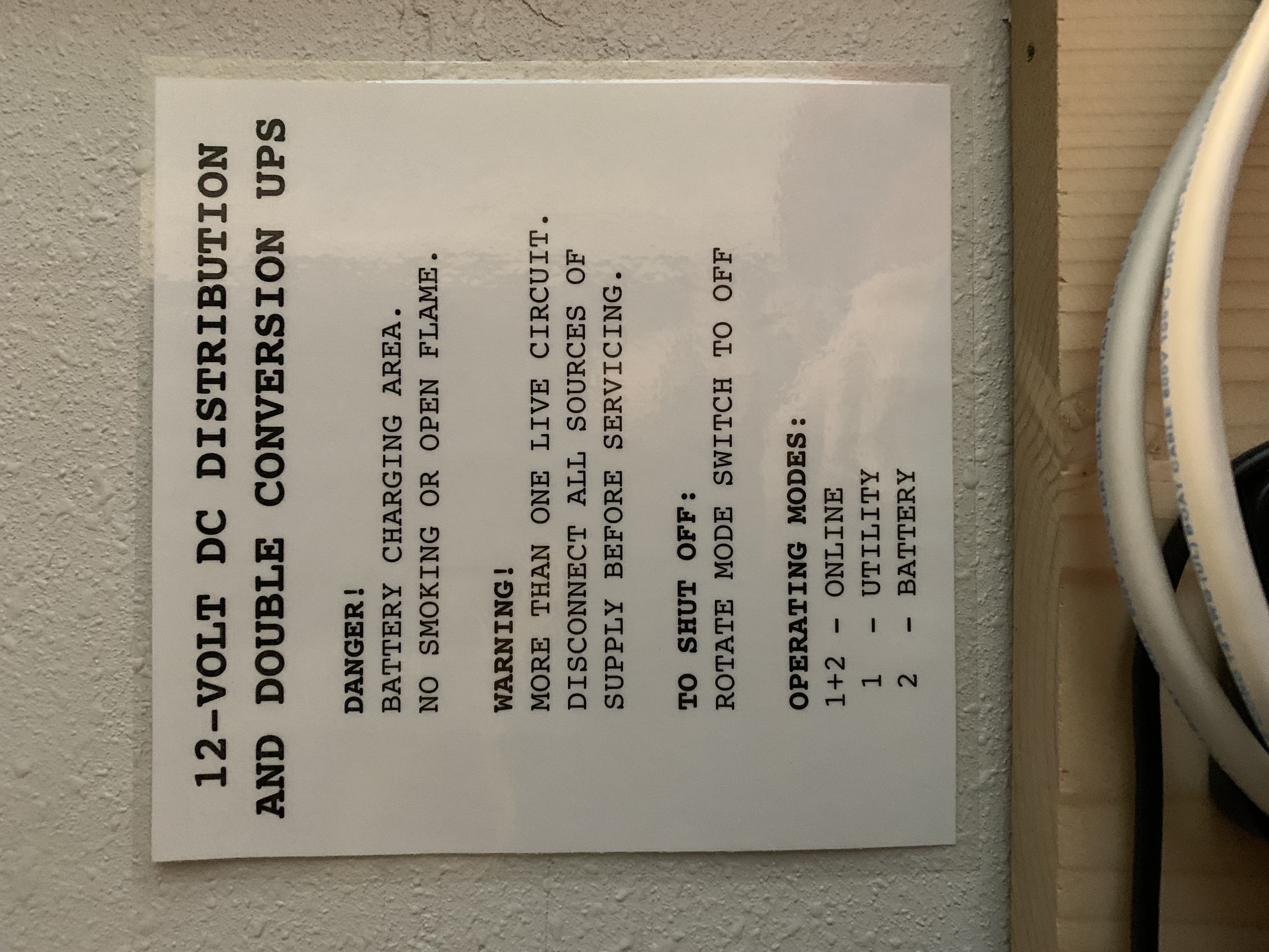
safety first!
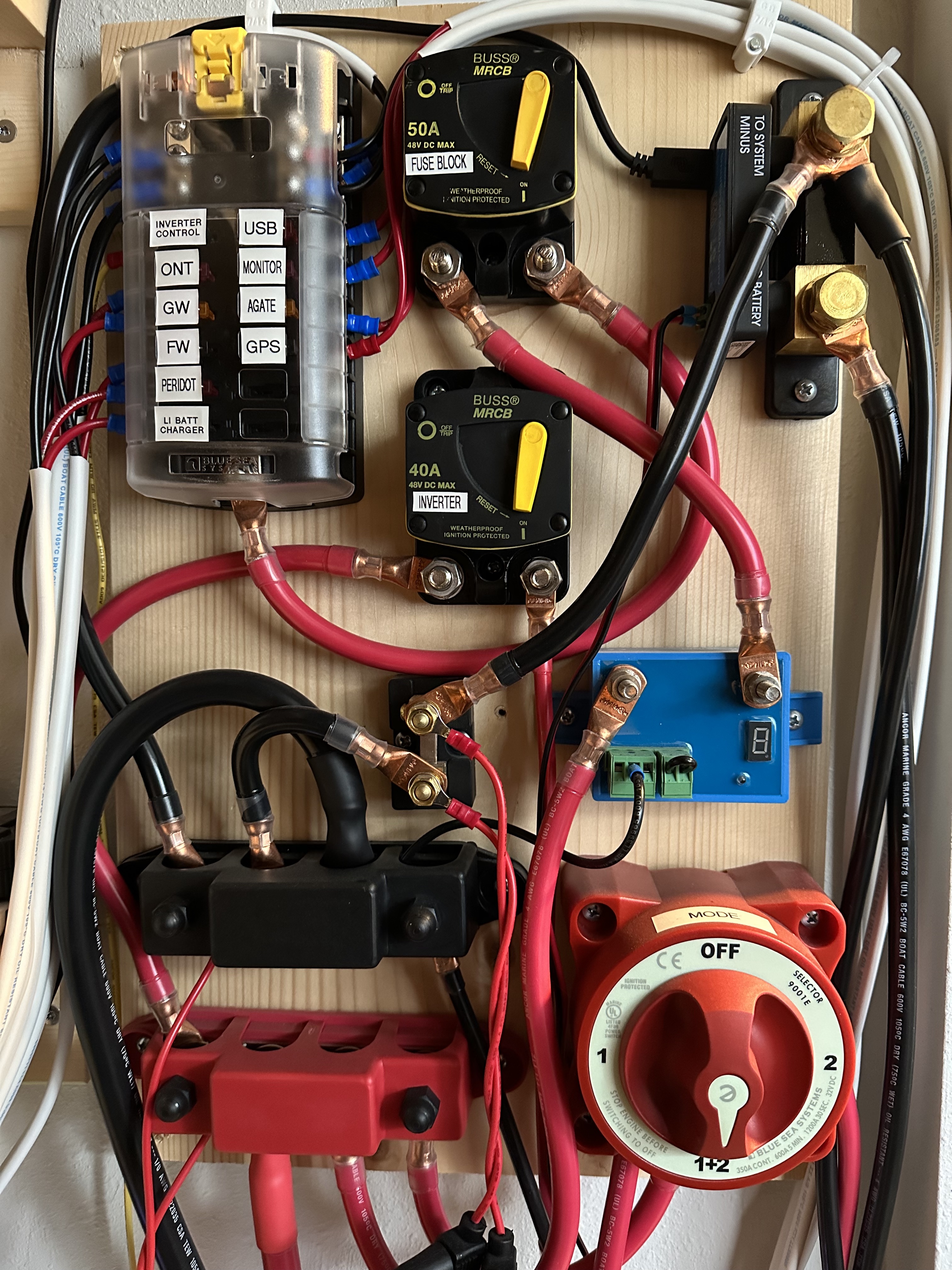
main panel
clockwise from top left: fuse block, main and inverter breakers,
smart battery shunt, battery protector, mode switch, main bus bars,
load shunt
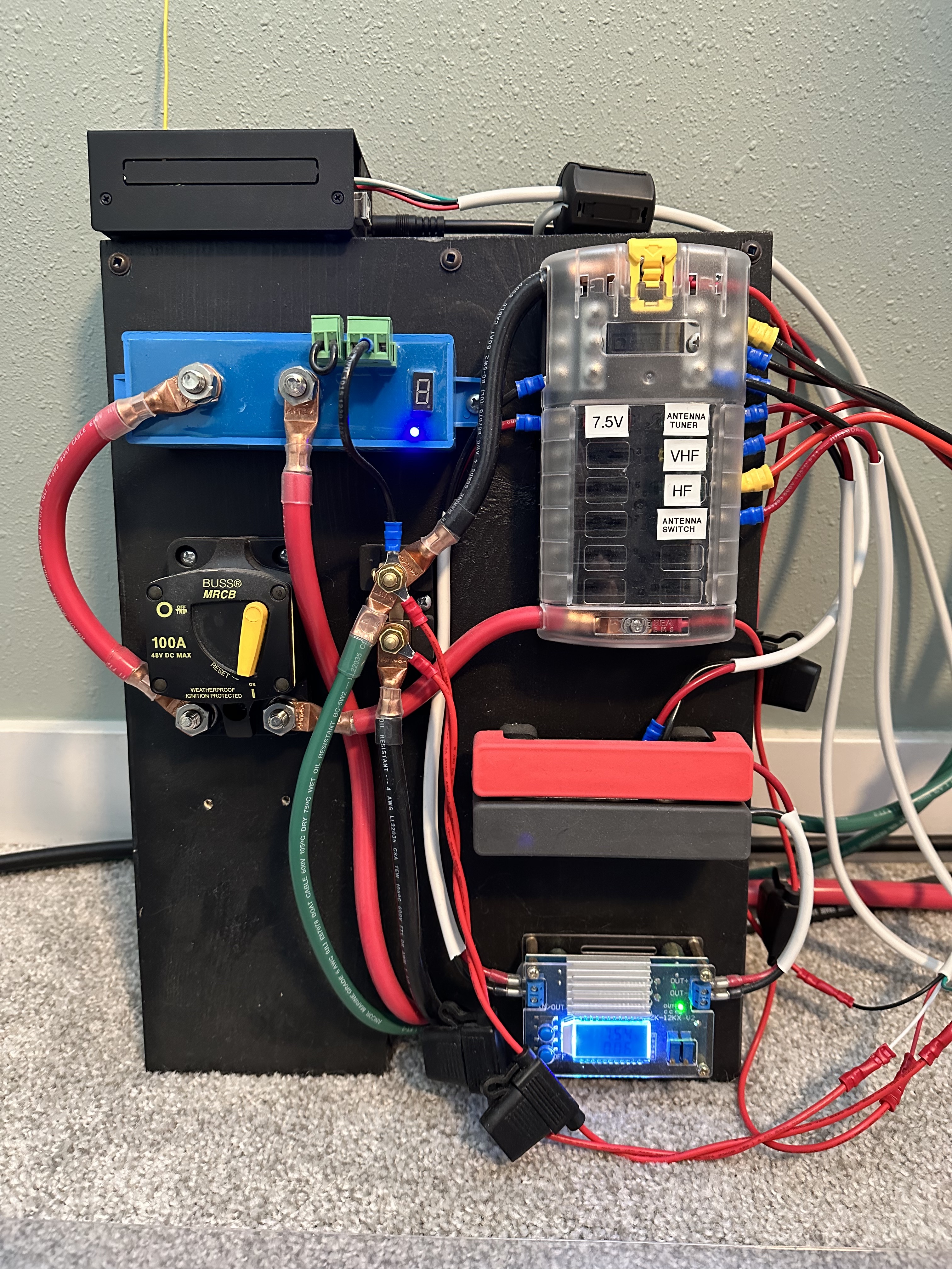
desk subpanel
clockwise from top left: battery protector, fuse block, 7.5-V bus bars,
buck converter (set to 7.5 V), main breaker, load shunt
above: Arduino monitoring system
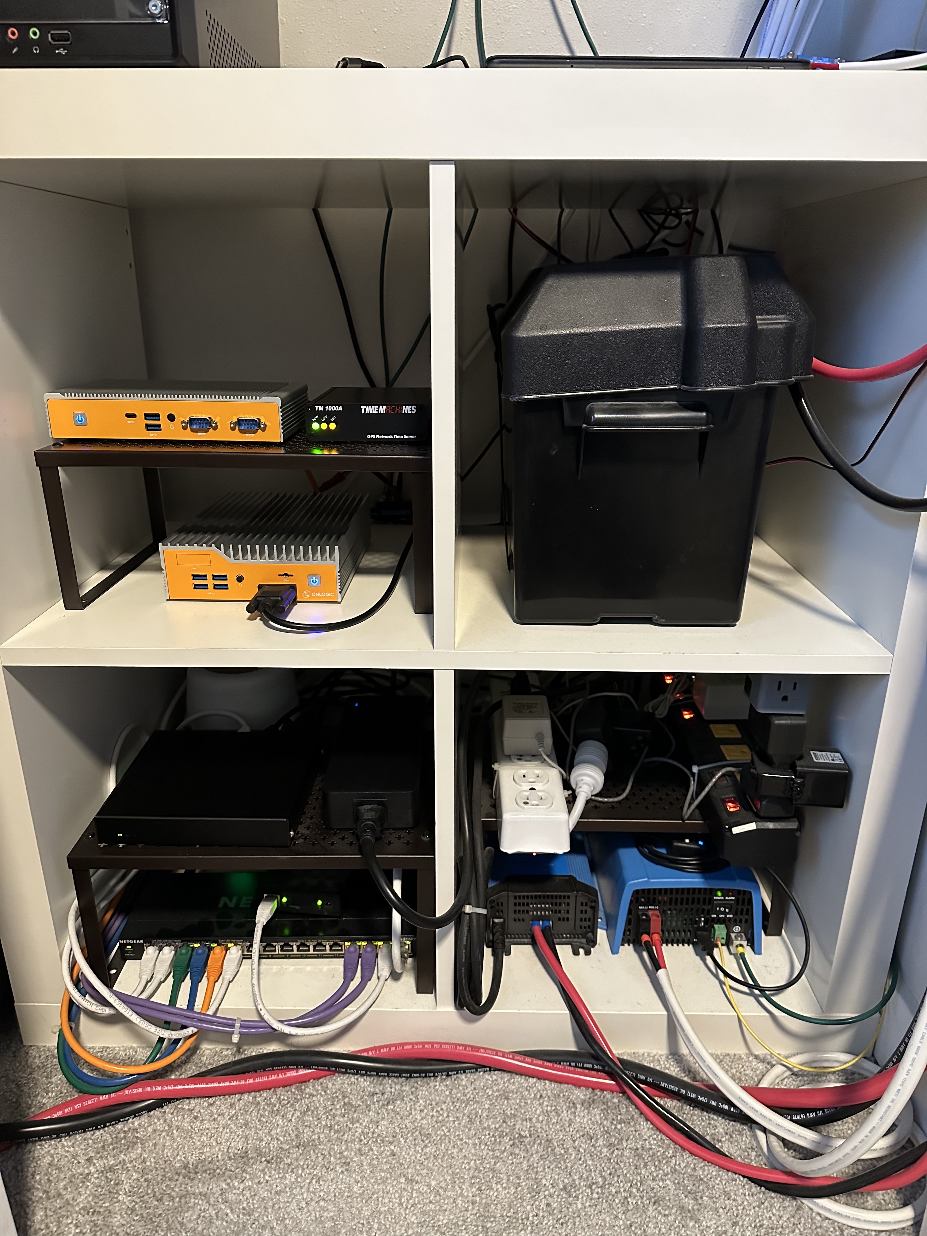
computing and electrical equipment
clockwise from top left: main frame, battery frame, power frame,
network frame
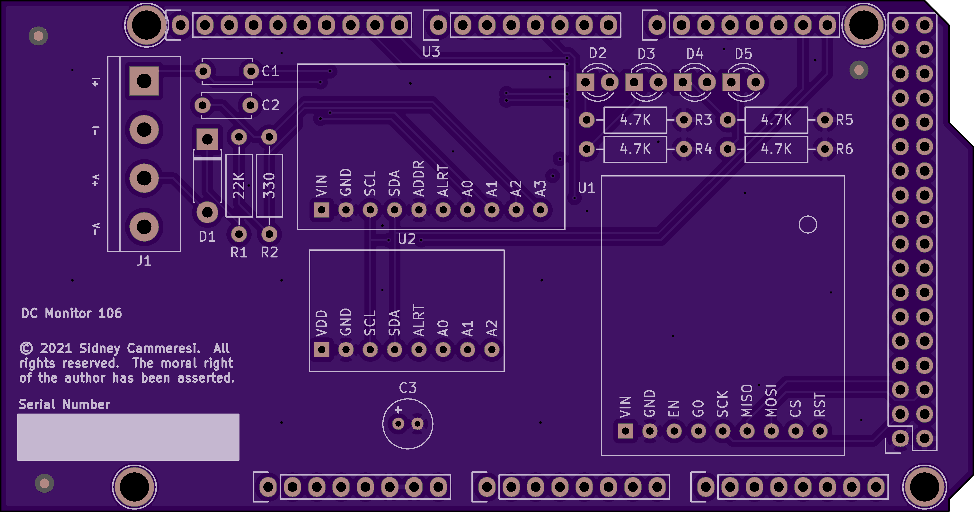
fabricator's rendering of the monitoring circuit board
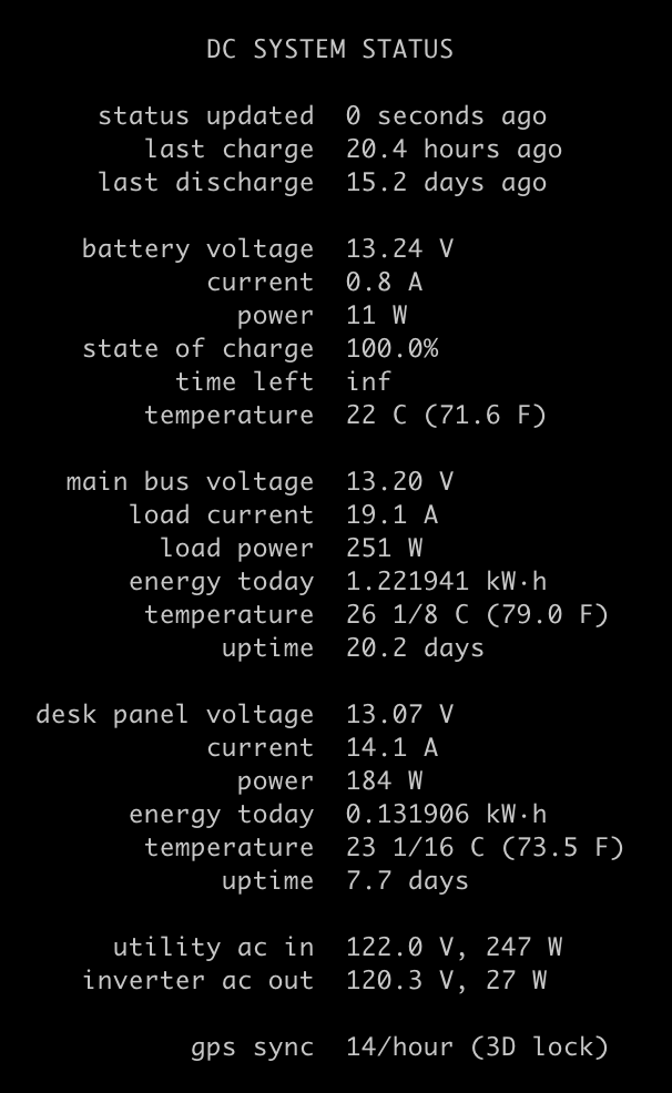
command line monitoring while transmitting on ham radio
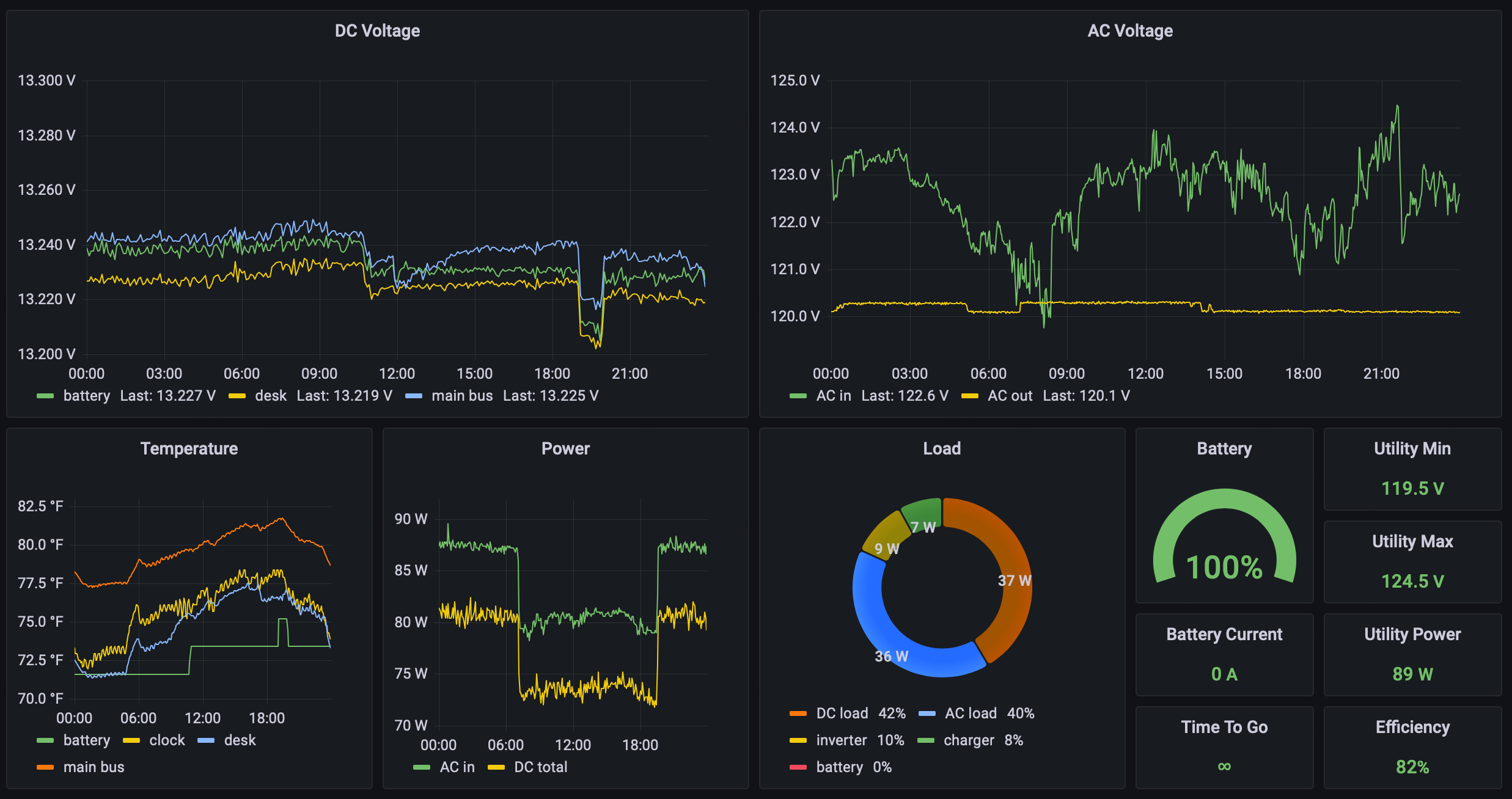
data science
Note how the utility input voltage varies over the course of the day while the inverter output remains nearly constant—the hallmark of a double conversion topology.
Note also the ripples in the temperature graph. While the absolute numbers are affected by localized heat produced by the monitoring devices, the high-precision (0.0625 ºC) sensors in the main and desk monitors reveal the cycling pattern of my furnace. The precisions of the clock and battery sensors are 0.25 ºC and 1 ºC.
Sid's DC Power System
Motivation
In January 2021, we moved to our current house (known as Greenmore) in Shoreline, Washington. In the course of moving my network and computing equipment, I wanted to make several improvements to my setup at the new place. My UPS was quite old, from 2012, so I needed at minimum a new battery, but I was also emotionally scarred by frequent power outages in Kenmore and wanted to significantly increase my runtime on battery to at least a few hours. With more battery capacity, I could take a more relaxed attitude to starting a generator.
My old UPS was an ordinary consumer-grade unit with a line-interactive topology, a modified sine wave inverter, and a rating of 1500 VA. Upon starting shopping for an improved UPS, getting a full sine wave inverter was easy, but almost nothing was available with greater runtime that wasn't rack-mount, expensive, and noisy. A further absurdity is that most UPSes are designed on the assumption that you will run at maximum power for only 20 minutes or so; thus if you want a bigger battery, you also have to buy a larger inverter.
In the course of this research, I discovered the double conversion topology, a UPS that has its charger, battery, and inverter connected in parallel and always active. In contrast, a line-interactive topology connects the load to utility power and then sits on the side and monitors the utility power; if its voltage goes outside of an acceptable range, the UPS activates its inverter and switches its output from utility to inverter. Your equipment is thus unpowered during this transfer time, which takes about 10 milliseconds. Hopefully your equipment can ride that out on its capacitors.
I liked the double conversion idea, but the implementations of it that were commercially available were totally impractical for home use. But what if I made my own? If I kept the system small and power usage low, I should be able to avoid activating cooling fans, thus keeping the system quiet. Additionally, I could power many of my loads directly from DC, reducing load on the heat-producing inverter. And if I built the system myself, I could use whatever size of battery I wanted.
Principle of Operation
The battery charger and battery are connected to the terminals on the battery switch. By turning the switch, one may connect the charger, the battery, or both to the system. The switch's output connects to the positive bus bar. To the bus bar are also connected the subpanel, the inverter breaker, and the battery protector. The battery protector monitors the system's voltage and shuts off its output if the voltage drops below a threshold. The battery protector is then connected to a main breaker that then connects to the fuse block. Normal devices are connected to the fuse block, which has small screw terminals and accepts normal automotive fuses. Negative connections are collected at the fuse block, which thence proceed to the negative bus bar, the load shunt, and the battery shunt. Shunts are very small resistors of known value across which one can measure a small voltage and thus infer the current.
The inverter cannot be connected to the battery protector because of the very large current its input-side capacitors draw when initially connected to power, but the inverter has a control circuit that is connected to the fuse block. Thus the inverter will still be shut off at the low voltage threshold even though it is connected directly to power.
Because the charger, battery, and loads are all connected in parallel, there is zero transfer time should utility power fail.
Construction
Since I wasn't fully sure I knew how to do this, I constructed the system gradually and incrementally over a few months, beginning in April 2021. Initially, there was no battery, and power was supplied by a ham radio power supply I already had. As early experiments succeeded, I progressively believed that I knew what I was doing, and I ordered more components. Later, I substituted the power supply for a real battery charger and then actually connected the battery. Initial installation and commissioning of the system took place in August 2021.
After some initial on-battery testing, I realized I needed real statistics about the system's performance, so I added the SmartShunt. All of the Victron Energy devices speak Bluetooth and can be configured and monitored via an iOS application. I also connected the SmartShunt to a computer and started writing a monitoring system to store various telemetry in a database.
Unfortunately, I had no way to monitor load because the charger had no serial interface, and Victron's Bluetooth protocol is proprietary and highly complex. (As of 2022, this may be changing somewhat.) So I dusted off my knowledge of Arduino and built a custom monitoring circuit to measure voltage, load current, and temperature. The circuit has some LEDs for status and a LoRa radio for communicating telemetry wirelessly. I eventually converted the circuit into a printed circuit board, which I had fabricated. It's not the cheapest board because I made it four-layer; someone who is a better electrical engineer could probably make it two-layer. But OSH Park will make three copies of it for only $84.
The monitoring device connects to a computer via USB and communicates with custom monitoring software. The telemetry data are stored in a Postgres database. I have both command line tools to check on the system, automated alerts when something goes wrong, and a Grafana dashboard with fancy graphs.
Monitoring AC didn't happen for a while because I couldn't find suitable hardware and building your own hardware for AC voltage is very dangerous. Eventually, I found and bought an IotaWatt. I connect one VT (voltage transformer) to utility power and another VT to the inverter. These are dumb 120 to 9 VAC transformers that the IotaWatt uses to measure voltage and frequency. Two VTs are necessary in this application because the waveforms of the utility power and my inverter are not synchronized. I also attached current transformers to the utility input and inverter output. The device is of course powered by the DC system itself for reliability.
At some point, I remembered my ham radio aspirations, and I thought that it would be neat to have backed up DC power at my desk to run ham equipment. Thus I extended the system to my desk by using giant 1/0-gauge wires as the feed to a subpanel. These wires are about half an inch in diameter. (If your house has 200-amp electrical service, the cable connecting your house to the utility pole is likely 4/0-gauge, only three sizes larger.)
Performance
I am very pleased with this system, which has excellent performance. My runtime on battery depends on load, which varies over time slightly, but I can easily expect the battery to last eight hours.
For fanless operation, minimizing load on the inverter relative to its capacity is fundamental. I bought a 500-VA inverter even though my maximum AC load is around 35 watts. But because the load is low, the fan never activates. Unfortunately, all inverters will waste about 1% of their maximum load when idling, plus a fraction of the load.
About half the load is DC, not passing through the inverter. In fact, my only AC device is a Power Over Ethernet switch. Everything else runs on unregulated DC (13.2 V most of the time, 12+ V on battery, 14.4 V while charging), 7.5 V regulated, or USB. POE is extremely useful for distributing reliable power to remote devices, although it requires AC input (or else a high, unusual DC voltage, required by its being passed through to powered devices).
My setup is now essentially fanless. Although the inverter has a fan, it is activated by temperature, and I have never run it hard enough to cause it to come on. The charger also has a fan, but it doesn't come on in normal use. The only time it comes on is when charging the battery after a long battery test. I also upgraded my backend computer to an industrial, fanless, DC-powered model from OnLogic, so no fans run at all in my closet, outside of exceptional circumstances.
Don't skimp on wire! I initially used 8-gauge wire for the charger, but after a battery test, the wire got quite warm to the touch. The tables and numbers said I was okay, but I decided to upgrade it anyway to 6-gauge, which gets barely warm when passing high current. My safety philosophy is to have vastly more margin than I could possibly need, so I vastly oversize all the wires.
However, 1/0-gauge was chosen for the subpanel feed not for safety but to minimize voltage drop. When my ham radio transmitter keys up at 100 watts, the 15-A current causes a voltage drop at the subpanel of only 160 mV from normal (35 mV of which is in the charger cable and main panel).
Future
One choice I would make differently today is that I would not buy an AGM lead acid battery. LiFePO4 batteries are significantly better in terms of weight (30 vs 50 pounds), lifetime (thousands vs hundreds of cycles), depth of discharge (90% vs 50%), and charging requirements (lead requires a very long charging régime and lead must go to 100% full regularly or suffer permanent damage). Lead's only advantage is cost (about half as expensive). Lead is still okay for standby use such as this, but everyone doing RV, marine, off-grid, or solar systems has switched to LiFePO4.
Main Panel Parts
- Victron Energy Blue Smart Charger (120 V in, 12 V @ 30 A out)
- Victron Energy Smart Battery Protect (12/24 V, 65 A)
- Victron Energy SmartShunt (500 A)
- Victron Energy Temperature Sensor
- Victron Energy VE.Direct to USB cable
- Victron Energy Phoenix Inverter (500 VA, 12 V in, 120 V out)
- Victron Energy VE.Direct Smart Dongle
- Blue Sea Systems 9001E battery switch
- Blue Sea Systems 187 Marine-Rated Circuit Breakers (50 A and 40 A, surface mount)
- Blue Sea Systems fuse block (12 circuits, with ground and cover)
- Bay Marine Supply MRBF terminal fuse block
- Bay Marine Supply battery terminal fuse (150 A)
- red/black pair of bus bars (250 A)
- current shunt (100 A, 100 mV)
- AGM deep cycle marine battery (12 V, 100 Ah)
- Seachoice battery box
- IotaWatt with additional VT
- Klein Tools 10x line splitters
Desk Subpanel Parts
- Victron Energy Smart Battery Protect (12/24 V, 100 A)
- Blue Sea Systems 187 Marine-Rated Circuit Breakers (100 A, surface mount)
- Blue Sea Systems fuse block (12 circuits, with ground and cover)
- current shunt (100 A, 100 mV)
- pair of junction posts to connect 1/0 to 4 AWG
- DROK buck converter (160 W max)
- small red/black pair of bus bars for 7.5 V
Monitoring System Parts
- Arduino Mega
- KKSB case for Arduino Mega with shield
- DC Monitor 106 (custom PCB designed by me)
- Adafruit ADS1115 breakout board (16-bit ADC)
- Adafruit MCP9808 breakout board (0.0625 ºC temperature sensor)
- Adafruit RF95 breakout board (915-MHz LoRa radio)
- DROK buck converter (160 W max)
- miscellaneous discrete parts for the PCB
- automotive wire fuse holders (for voltage/current sensing wires)
Wire Sizes
- 1/0 AWG - feed to desk subpanel
- 4 AWG - default size for most wiring
- 6 AWG - charger (due to terminal size)
- 8 AWG - inverter (due to terminal size)
- 14 AWG - most branch circuits
Miscellaneous
- Ancor marine grade wire
- Selterm large copper ring terminals (per gauge; 1/4, 5/16, and 3/8 diameters)
- red/blue/yellow crimp terminals
- insulated ferrules
- automotive (ATO/ATC) fuses
- 5x20mm cartridge fuses
- heat shrink
Links
- Low←Tech Magazine — web site hosted in a Barcelona apartment, powered by solar
- Nine Reasons Why DC May Replace AC

Copyright © 2022 Sidney August Cammeresi IV. All rights reserved.
This content may not be reproduced in any form or manner without the express
written permission of the author.
The moral right of the author has been asserted.